
Making BIM tangible: Our experience within a challenging project
Alexandre Marques (1), Ana Rei (2),
Alejandro Romero (3), Hélder Pereira (4)
(1) Hilti Portugal, Porto
(2) Hilti Portugal, Porto
(3) Hilti Nederland B.V., Rotterdam
(4) Grupo Ramos Ferreira Engenharia, Porto
Abstract
With the growing adoption of the BIM methodology by the AEC (Architecture, Engineering and Construction) Industry, Hilti, as a company strongly connected to innovation, has cemented collaboration with reference companies and participation in relevant projects worldwide.
One of these partnerships is with Grupo Ramos Ferreira, a company with great experience in the design and execution of special installations. Ramos Ferreira and Hilti are collaborating in the construction of the Odense Hospital in a BIM environment, in this project that will be the largest hospital in the South of Denmark, with an investment value of around 600 Million Euros.
The current paper aims to describe the collaboration between Hilti and Ramos Ferreira, particularly in the definition of the support structure of the Mechanical and Hydraulic trades. Thus, the collaboration process in a complex context is described, as well as the design according to Eurocodes and a local Standard (DS 428-2019), the project optimization, phasing and coordination with logistics and the creation of Shop Drawings and the corresponding impact on the assembly of structures.
Finally, a self‑evaluation of the work developed is carried out, namely with the identification of the main challenges, benefits in the design and construction phase and next steps in order to improve productivity and security on the jobsite.
1. Project Framework
1.1. Hilti BIM Design Services
Hilti aims to make construction work simpler, faster and safer, with products, systems, software and services that provide clear added value. Hilti’s brand stands for quality, innovation and direct customer relationships. This mindset drives the company to invest approximately 6 percent of annual sales into research and development [1].
One example of Services provided by Hilti is related to BIM. BIM is used to plan pipes, ducts and cables, however the matching mechanical, electrical and plumbing supports are often not considered in the design stage and, thus are not on the BIM model. As a result, each trade commonly defines their own supports more based on experience rather than Engineering, which impacts in terms of coordination, waste of material, too much time invested in ordering material, etc. [2]. With the goal to improve productivity along the entire workflow including definition, installation and operation/maintenance of MEP systems, Hilti has developed BIM Design Services, which include the Design, Modelling and Output creation of MEP supports in a BIM workflow. Figure 1 shows the progress of the model along with the development of the different services [2]. Hilti’s scope starts with previously coordinated LOD 300 Project Models, adding next a new layer of information to the MEP models with the supports, having a final model with a high LOD – LOD 400 [3].
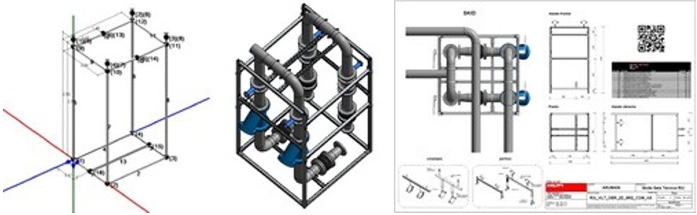
Figure 1: Progression of BIM Services – Design (left), Modeling (middle) and Output Extraction (right).
The stakeholders of the construction industry do not want BIM for itself, it always should be a mean to an end, and for Hilti these ends called BIM Use Cases.
The Use Cases powered by the BIM are [2]:
- Design optimization: with the study of different solutions and the adoption of multi‑trade supports – later described in the current paper;
- Pre-fabrication: enabled by the shop drawings and coordinated models;
- Advanced logistics: Coordinating the logistics with the bill of materials;
- BIM-to-Field: usage of measuring tools to layout the positioning of the supports based on spacial parameters on the BIM model;
- Validation: better management of documentation and monitoring of the jobsite through the BIM model;
- Field-to-BIM: importing jobsite information into the model with Hilti’s scanner.
Every year the pipeline of projects in which Hilti collaborates gets stronger, as this paper describes the collaboration with Ramos Ferreira, a leading company of design and execution of MEP installations, in a challenging project: the new University Hospital in Odense, Denmark.
1.2. Project Information
The Odense Hospital is part of a large structural reform for the Danish Healthcare System. It will be the largest new Hospital in Denmark built from scratch, with a ground floor of approximately 286,000 m2 and with 849 beds [4].
Ramos Ferreira is the company in charge of the execution of the Mechanical and Hydraulic Trades of Central Building (DP03), shown at Figure 2.
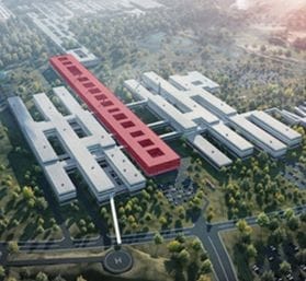
Figure 2: The Odense Hospital, with the Central Buikding (DP03) shown in red.
1.3. Project Scope and Analysis
As shown in 1.2, Ramos Ferreira is working in the Central Building of the Odense Hospital. In this building there are different areas that distinguish for being more complex, which are the corridors, shafts and technical areas. As so, these were the areas considered under the scope of the BIM Design Services.
For the corridors, common trade solutions (supports that integrate both mechanical, electrical and plumbing trades), with a 2-meter spacing, were already defined by Hilti Italia for the General Contractor of the Project. However, as defined in the Danish Standard DS 428-2019 [4], there is a need to have intermediate supports between the common trade supports. As so, our scope was to study: (i) the intermediate supports of the corridors, (ii) supports of the shafts and (iii) supports of the technical areas.
Regarding the analysis of the project, the first step was to estimate the number of hours needed to execute the project. For this, it was performed a deep analysis, with the measuring of the different corridors, shafts and technical areas on the software Navisworks – see Figure 3.
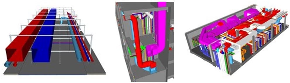
Figure 3: Example of corridors (left), shafts (middle) and technical areas (right) identified and measured.
With the measuring of the project, we also identified different types of solutions for the project (for example single point supports, U-frames, multi-trade supports, etc.) in which, for every type of solution, we have a benchmark of number of hours needed for design, generation of input to the modelling team, QA/QC, modelling and production of output from the BIM model.
From this study we estimated more than 1800 hours to execute the project, separated by the different tasks, supporting us on the planning of the project.
2. How we collaborate
2.1. Mobilization plan – team involved
In order to assist the execution of large and complex projects, like the Odense Hospital, Hilti has a BIM Competence Center, in Rotterdam, in which a very experienced team supports the market organizations. The BIM Competence Center of Hilti has the accreditation of ISO19650 [6].
A team of 10 people, from Hilti Portugal and the BIM Competence Center, was mobilized to execute this project. The team in Portugal consists of a BIM Project Manager, responsible for the project management, and two BIM Lead Engineers, which ensure the correct design of the MEP supports. From the BIM Competence Center there is an International BIM Project Manager, responsible to coordinate the team in Rotterdam, an International BIM Lead Engineer, which supports the team of designers in Portugal, a BIM Lead Modeller, which supports the Modelling team, composed by four modellers.
To ensure a good communication between the different teams, including the BIM Managers from Ramos Ferreira, is essential to have a good collaboration process.
2.2. Collaboration process
In order to ensure a good communication, is relevant to have an effective central repository where the construction project information is housed and shared through the different teams involved – the Common Data Environment (CDE). The CDE selected for this project was BIM 360, from Autodesk.
For the definition of the MEP supports, is vital that the project is coordinated upfront, without clashes between the different trades. To guarantee so, it is used the “Design Collaboration” functionality of BIM 360, where the BIM project models are “consumed” once they are coordinated and published by the different teams. After consuming the models, we link to our BIM model and start the design.
One major aspect that has a big impact within our productivity is that the project is divided into different Building Blocks, which makes our BIM models lighter and, therefore, faster to work. We have one central model for each Building Block, allowing us to work in an efficient way simultaneously by different teams.
The input to the modelling team and the QA/QC process (deep dive on these processes in chapter 3.3 of the current paper) is performed by the BIM Lead Engineers and communicated to the modelling team through BIM Track. BIM Track is a web‑based issue tracking platform, that allows continuous coordination and keeps the project team updated about the issues open and closed – see Figure 5. Each issue created on BIM Track is connected to a specific Level, Phase, Discipline or Team involved, which makes it possible to have clear view on the different issues along the execution of the project. This platform is used by the Design team to communicate the input to modeler (information that the modelling team needs) and also the quality control of the models and output (drawings and bill of materials). A package is only delivered to Ramos Ferreira once all the issues are closed, so we have a guarantee that the output is according to the design. In Figure 4 it’s possible to see a chart with the different issues according to the building blocks (phase of the project).
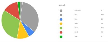
Figure 4: Issues sorted by phase of the project.
The output – design reports, BIM models, drawings and Bill of Materials are also shared through the CDE. An overall scheme of the collaboration process is presented at Figure 5.
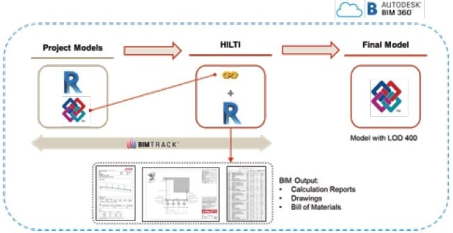
Figure 5: Overall scheme of the collaboration process.
3. From model to execution
3.1. Design of MEP Supports
The MEP supports are essentially small steel structures, in which the structural design must be carried out to ensure that they comply with the current regulations. The design is performed with the support of the software Hilti Profis Installation – see Figure 6. Profis Installation does the verification of the steel members of the supports according to Eurocode 3 [7].
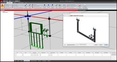
Figure 6: Design example of a support on Profis Installation.
Alongside the verification according to Eurocode 3, some extra requirements were also considered, according to the Danish local standard DS 428-2019 [5]. These requirements are related to the maximum spacing between the mechanical supports and other specific details, like the minimum threaded rod diameter for the supports.
The design criteria assumed is also influenced by the location of the supports. At the corridors, since we are only considering intermediate supports between the main supports, as stated in 1.3, the design only considers the self-weight of pipes and ducts, including water and insulation.
However, in the Technical Areas and Shafts, since the project has pipes with large diameters, thermal expansions phenomenon’s must also be taken in account, to effectively control the displacements of the pipes.
When designing the supports, the goal is to achieve the optimal solution and provide the required inputs for the modellers to initiate the modelling process. The input to the modelling team needs to have all the information needed for later ordering and prefabricate the MEP supports, namely all the accessories needed, including non-graphical parameters, like the item number.
3.2. Solution Optimization
In order to identify the optimal solution for each situation, there are more parameters to consider than the cost of the material (hardware cost), namely the time and effort needed to assembly and install the supports (labour cost).
As so, during the design phase, multiple solutions can be studied for one application, considering the hardware cost and the labour cost. In the end these two different costs are summed in order to identify the global cost for the solution and, consequently, the cost optimal solution. For example, some accessories can have a higher cost comparing to others but be much faster and simpler to assembly (lower labour cost), which makes the solution, in the end, more suitable.
One example of this study carried out by our Engineers during the design is shown at Figure 7, with the comparison of five different solutions for the same application.
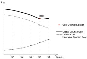
Figure 7: Coast optimal solution study – schematic representation.
Another topic that our team optimizes during the design is related to multi-trade supports. Traditionally, each trade works independently from each other, and defines their own supports and subsequently installs them at different points in time. Hilti follows an optimized project approach, striving to organize the mechanical and hydraulic trades into the same support – Hilti’s multi-trade supports. In Figure 8 it’s possible to see one example of a multi-trade support defined by Hilti.
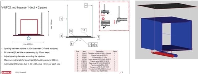
Figure 8: Example of a multi-trade support defined by Hilti with mechanical (duct) and hydraulic (pipes) trades: input to modeler (left) and support in the model (right).
3.3. Quality assurance & Quality control Process
Hilti’s commitment to Quality assurance & Quality control (QA/QC) is based on the ISO 9001 certification [8]. All the BIM Lead Engineers have a clearly identified QA/QC process that takes place in two different occasions: (i) at the end of the modelling process and (ii) at the end of the production of BIM Output (drawings and bill of materials). This ensures that all the outputs from the BIM model are according to the quality requirements before sharing with Ramos Ferreira in the Common Data Environment.
As mentioned in the collaboration process, all the issues are communicated through BIM Track. With this process all the issues are treated as soon as possible, and an effective dialogue is achieved. The entire process is visible to all the relevant personal, which is relevant to guarantee that the proposed solutions fit all the parties involved.
3.4. Shop Drawings
The drawings of the MEP support solutions are generated through the BIM model. This fact, combined with the QA/QC process previously described, ensures high output quality and enables the prefabrication/pre‑assembly of the supports.
The supports are defined with two different types of drawings: (i) a plan view identifying the position of the supports superimposed with the architectural layout and (ii) a section parametric drawing, which contains different tables with the parameters on the drawings, making possible the prefabrication with the minimum number of drawings and leading to high savings in labour costs. An example of the drawings generated is show at Figure 9.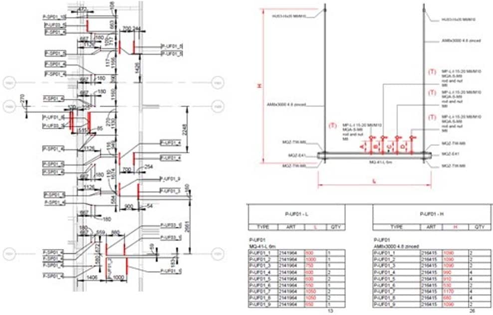
Figure 9: Example of drawings generated – plan view (left), section view (top right) and table with parameters (bottom right).
3.5. Phasing and Advanced Logistics
The world is facing challenging days, within a global pandemic context. The Covid virus is having an impact on different factors, namely in the logistics and stock material.
To minimize the impact of the pandemic context in the milestones of the project, it is essential to have a clear communication between our BIM Lead Engineers and our Logistics department, to make sure we are defining solutions and blocking hardware for the project in the warehouse at the same time.
For a successful logistics operation, BIM is vital. Our BIM models include all the pieces needed to assembly the supports, so the Bill of Materials is automatically extracted from the BIM model and has no human error. It was defined by Ramos Ferreira and Hilti a periodic delivery of hardware in Denmark (approximately every two months), so the material is being delivered for the different building blocks along the time. This also helps Ramos Ferreira to control the space they have for stock on the jobsite.
When there is a big mismatch between the quantity of material needed for the project at a time and the minimum order quantity (more than 10%), the remains are considered for the next orders of material, making sure we achieve high savings of material and minimize waste.
4. Our experience so far
The development of a LOD 400 model on the MEP trades of a project can have a big impact on the savings and productivity of a project. While defining the MEP supports upfront in the Odense Hospital, even though the project is still in progress, we have been identifying a lot of added value for Ramos Ferreira, namely:
- Better coordination of the different trades and among contractors – no definition of support solutions on the jobsite;
- Savings on hardware (estimating up to 30%) due to the definition of the MEP supports ‑ Ramos Ferreira has a precise bill of materials, which allows a detailed material ordering instead of a bulk ordering with high material waste;
- Savings on hardware due to the multi-trade support approach (mechanical and hydraulic elements with the same support) – Estimated savings of approximately 1400 supports, 2800 anchors and, consequently, 700 hours of assembling supports and 110 hours of drilling on all of the Central Building;
- Savings on assembly time of approximately 610 hours, due to the usage of the shop drawings for assembling the supports (estimation for all of the Central Building);
- Improved Logistics, minimizing the impact of the pandemic on the delivery of material on the jobsite and meeting the demanding project deadlines.
The added value mentioned above clearly justifies the Return of Investment (ROI) on the BIM Design Services. With our experience in this project, one key takeaway is the relevance of defining upfront the BIM Uses for the project. With a clear view about how can BIM support us in the different stages, is possible to convert the powerful information in the BIM model into productivity in the jobsite. The challenging experience within this project is also supporting Hilti on optimizing our BIM processes, to be more and more productive.
References
[1] Hilti, Company Profile, accessed December 14, 2021, https://www.hilti.group/content/hilti/CP/XX/en/company/corporate-information/company-profile.html.
[2] Cerny, Pavel and Marques, Alexandre, “Redeeming BIM’s Promise in Practice: Integrative Planning with Hilti as a Partner”, PTBIM 3º Congresso Português de Building Information Modelling, Porto, pp. 123‑124, November 2020.
[3] BIMForum, Level of Development (LOD) Specification For Building Information Models, December 2021.
[4] Nyt OUH, The New University Hospital in Odense, accessed December 15, 2021, http://www.nytouh.dk/english.
[5] DS 428:2019, Fire Protection of Ventilation Systems.
[6] ISO 19650‑1:2019, Organization and digitalization of information about buildings and civil Engineering works, including building information modelling (BIM).
[7] EN 1993‑1‑1, Eurocode 3 – Design of steel structure – Part 1‑1: General rules and rules for buildings.
[8] ISO 9001:2015, Quality Management Systems Requirements.